C2 -- ZAI demo D2 concepts
NOTE: This page was converted from docx to markdown+png’s by GPT 26.0826 (minimal patchup required afterwards).
GPT: I still have them from our work here, so **you don't need to find your notes**.

For the last DOCX (Phase 1), the main rules were:

* DOCX → **one Markdown file + PNG images → ZIP**
* Image marker such as `D1_320` becomes:

  \```html
  <img src="/assets/D1/D1_320.png" alt="xxx" width="..." style="border: 1px solid #999;">
  \```
* Use the existing `D1_###` identifiers as PNG filenames.
* Choose image width reasonably based on screenshot size/content.
* DOCX H1 → `# **xxx**`
* DOCX H2 → `### **xxx**`
* DOCX H3 → `#### **xxx**`
* DOCX H4 → `**xxx**`
* Add `<br>` before H1–H3.
* Ignore manual Word page breaks.
* **Consecutive bullet items have no blank lines between them** — this was the correction you made on the last conversion.
* Package `.md` + `/assets/D1/*.png` into a ZIP.

So if you're about to give me another DOCX, I can use the **same conversion rules as the final Phase 1 version**.
I can easily update this from the docx (new text/pics tagged) by doing the following:
- 1 Submit current md (markdown) file + tagged docx.
- 2 Tell GPT to
  - add only the new tagged text in the docx to the md file.
  - create only new png's.
- 3 Then upload to the webserver the new version of md file (overwrite) and the new png's.
Its that simple with AI. There is usually some minor cleanup, but not much.
C1 Demo D2 concepts (to be converted to markdown by GPT)
(26.0825 rough draft; markdown text generated from MS.Word docx source file using GPT).
NOTE: P1/P2 are the parts with AI (P3 does not involve AI).
TOC:
- C1.1 Foundry FDE (an amazing tool that is proof that AI is no bubble)
- C1.2 P1-P3 overview diagrams
- C1.3 P1 UI TOP/BOTTOM (AI/RAG)
- C1.4 P2 LEFT (display chunks that match userQuestion via embeddings)
- C1.5 P3 RIGHT (create diagram with linked keywords-chunks / NO AI)
C1.1 Foundry FDE (an amazing tool that is proof that AI is no bubble)
FDE is a critical tool. When you run into problems you simply submit screenshots and text. FDE can “see” screenshots. This has revolutionized how you work with Foundry.
Diagram 1: FDE can “see” screenshots/diagrams added to prompts
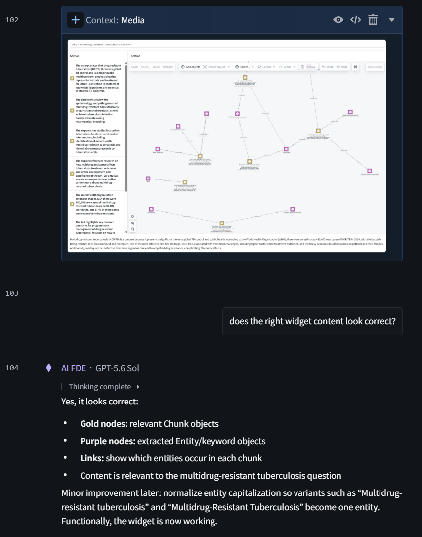
This is why the race for AI is no bubble. There are massive investments in infrastructure and energy because the bigger the patterns are that are used for content classification in the transformers, the more accurate the responses. I takes a lot of power to add another 9 to 99.999…%.
In the future you will probabl be able to voice, hand guestures, etc. To truly interact with the AI tools. This will required a massive amount of GPU compute. But it will be worth it. You direct, and AI gets it done. But you will have to direct. It only requires more massive brute-force pattern matching (GPUs+memory=power).
C1.2 P1-P3 overview diagrams
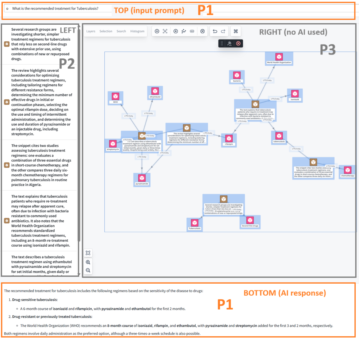
P1-P3 = the 3 phases of this demo (the original demo was just one long phase).
- P1 is 90% of the important AI-related parts of this demo. This consists of the top widget question and the bottom widget answer.
- P2 is a simply LEFT widget display RAG chunk text that was used to answer the question.
- P3 is the RIGHT widget. This is a vertext graph that does not use AI. In the demo below:
- Brown icons represent chunk text (input RAG text chunks “cleaned up” by AI).
- Purple icons are simply keywords/phrases that AI selected that are linked to chunks that contain them (simply keyword match).
C1.2.1 The 3 phases in the resulting UI
Diagram 2: P1-P3 = the 3 phases of this demo
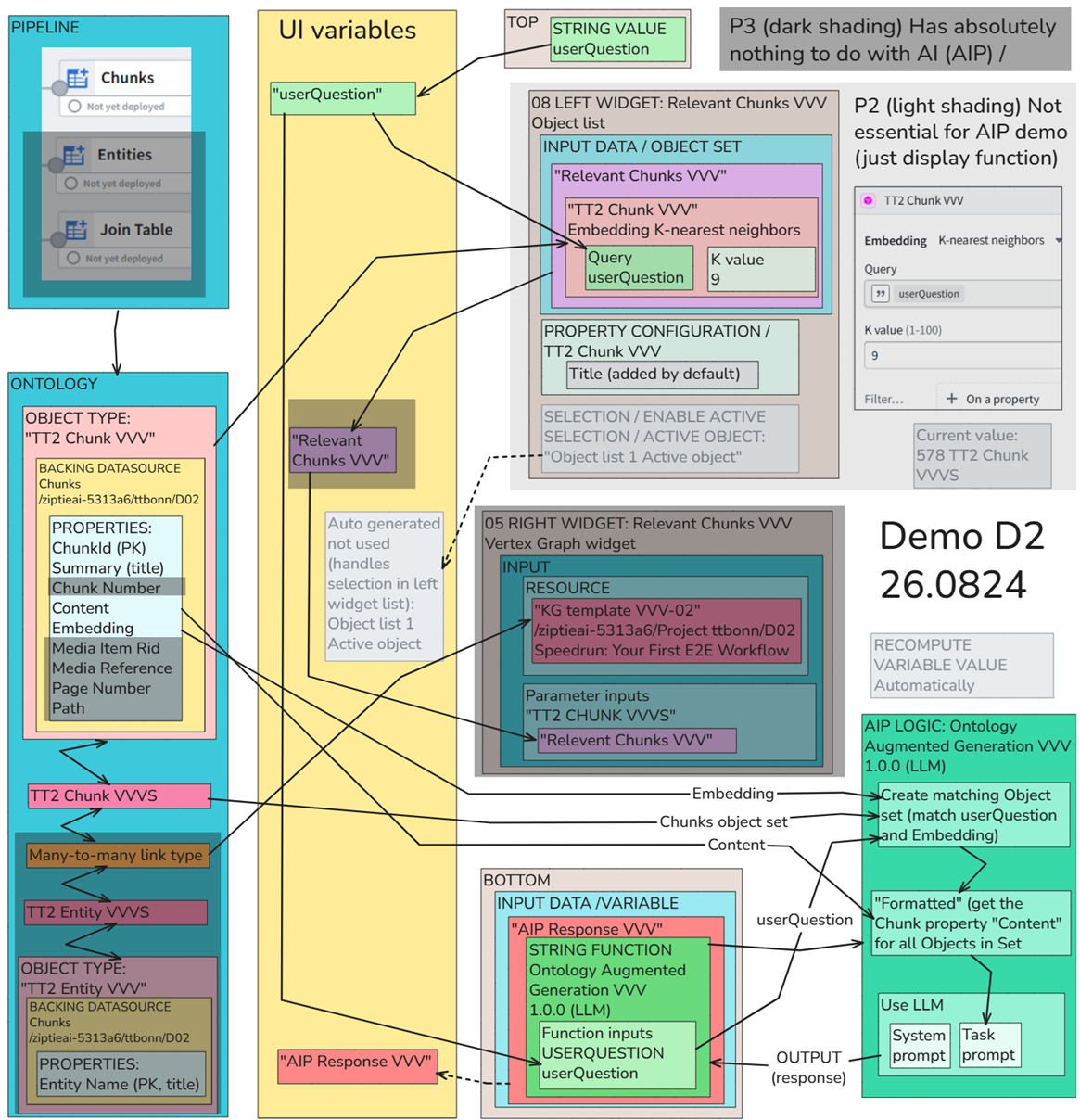
C1.2.2 The 3 phases in the system overview (pipeline, ontology, AIP, UI)
- The diagram shows that are basically 2 parts that dont depend on each other.
- The bottom widget response takes the top widget input and uses an LLM to answer the question with the RAG input.
- The left and right widgets do the complicated part
- Left widget takes the query text and compares against the embedding values in the “TT2 Chunk VVV” object type. It outputs to variable “Relevant Chunks VVV” the top 9 matching embeddings.
- Right widget takes the relevant chunks and inputs to the Vertex template for display.
- What this means is you could have done this demo from start (pipeline) to finish (UI) in 3 parts.
- First LLM (top and bottom widgets).
- Then display the nearest embedding neighbors (left widget).
- Finally build the template and add to the right widget.
- That would make it easier to handle all the complexity and not get stuck.
- But best of all would be to have this as an example. You install 2 working example instance. Use one as a reference and slowly rebuild parts of the other.
Diagram 3: The 3 phases in the system overview (pipeline, ontology, AIP, UI)
C1.3 P1 UI TOP/BOTTOM (AI/RAG)
(26.0825 this is a rough draft generated from skeleton content from a docx file)
TOC:
- C1.3.1 Master diagram for RAG/AIP (top/bottom)
- C1.3.2 Pipeline
- C1.3.3 Ontology chunks
- C1.3.4 AIP logic (RAG setup and model prompt/response)
- C1.3.5 UI (built in Workshop)
C1.3.1 Master diagram for RAG/AIP (top/bottom)
- THIS IS FASCINATING!! FDE/GPT-5.6 Sol analysis of diagram 1 (FDE can “see” screenshots!!):
- NOTE: RAG = 2. R-etrieval 3 A-ugmented 4 G-eneration
FDE:
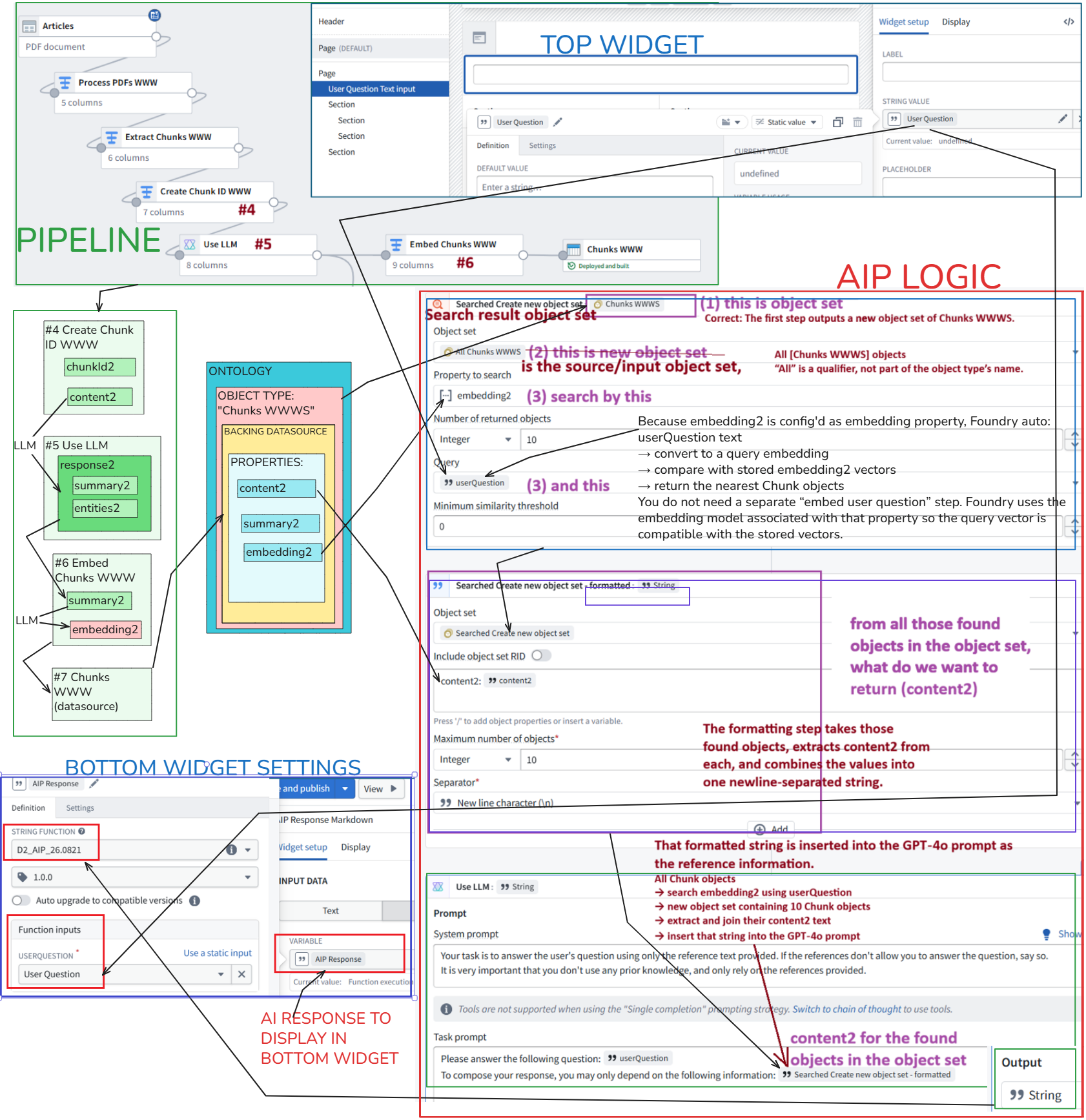
The diagram accurately captures the complete AI flow in Demo 2.
The optional Entity/Vertex branch is separate from the answer flow.
Your diagram now explains the core architecture far more clearly than the original Demo 2 documentation.
1 Offline preparation
- LLM creates summary2 and entities2.
- Embedding model converts summary2 into embedding2.
- content2, summary2, and embedding2 become Chunk properties.
2 Runtime retrieval
- The top widget supplies userQuestion.
- Foundry embeds the question and searches embedding2.
- It returns 10 matching Chunk objects.
3 Runtime augmentation
- AIP Logic extracts content2 from those objects.
- It combines the text into one reference string.
- That string is inserted into the prompt.
4 Runtime generation
- GPT 4o generates the answer.
- The function returns a string.
- Workshop stores it in AIP Response and displays it in the bottom widget.
Diagram 4: AI config workflow (P1-1, P1-2, … are sections in the docx)
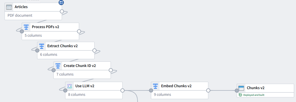
C1.3.2 Pipeline
(TODO: Describe the core concepts – the AI in nodes #5 and #6).
Diagram 5: The P1 portion of the pipeline
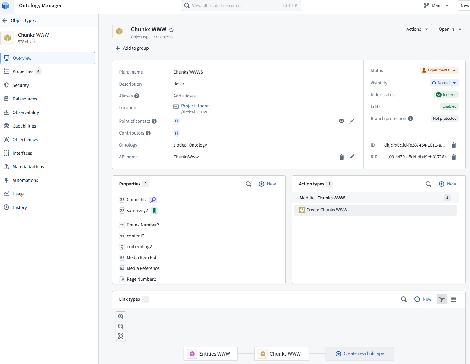
C1.3.3 Ontology chunks
(TODO: Describe the core concepts).
Diagram 6: The P1 portion of the ontology
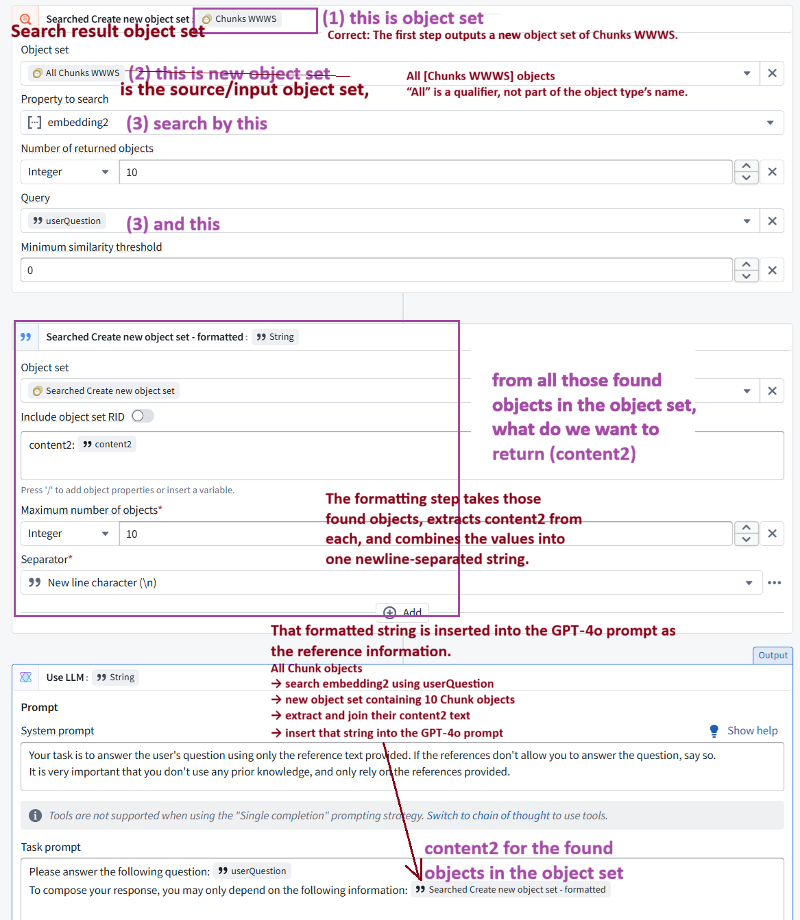
C1.3.4 AIP logic (RAG setup and model prompt/response)
Foundry converts document chunks into embeddings. When a user asks a question, Foundry retrieves the chunks with the most similar embeddings and inserts their original text into an LLM prompt. The LLM generates a grounded answer from that text. Separately, extracted entities connect chunks in a knowledge graph that users can explore alongside the answer.
Diagram 7: AIP logic core setup (need a clean diagram)
C1.3.5 UI (built in Workshop)
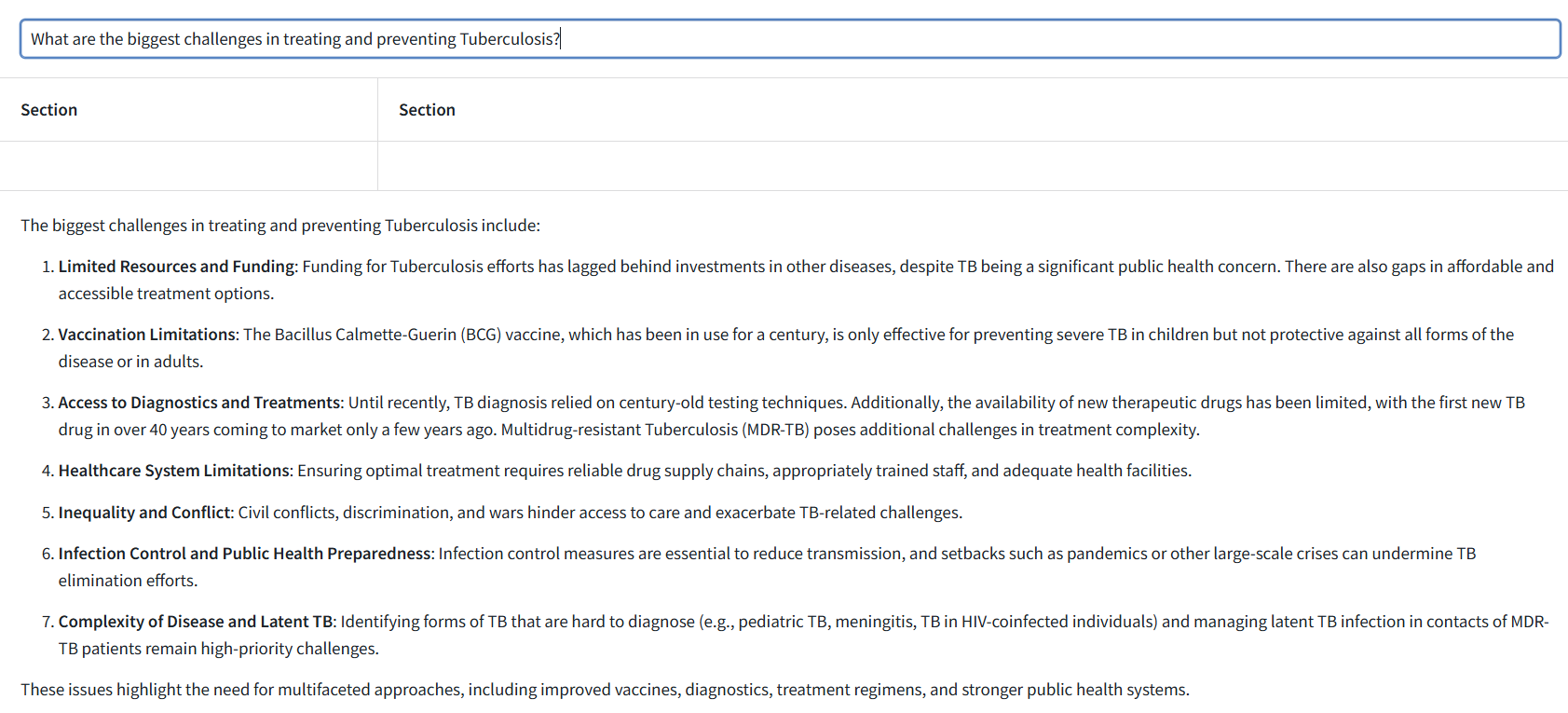
(need to update with numbers)
- TOP widget: Enter question about tuberculosis.
- The answer is then generated in the AIP logic based on the chunk embeddings (created by AI in the pipeline) that are the closest match to the embedding of the userQuestion (RAG). The model is remote (outside the enterprise).
- BOTTOM WIDGET shows the answer.
Diagram 8: The question (top) and answer (bottom) in the UI (the 2 empty section will be completed in P2 and P3)
C1.4 P2 LEFT (display chunks that match userQuestion via embeddings)
- This is the setup for the LEFT WIDGET
- INPUT DATA OBJECT SET = “Relevant Chunks” (var)
- The “definition” of the object set is “Chunks WWW” (an ontology ‘object definition’)
- Filter on propety “embedding2” which is
- The AI embedding of “summary2” which is
- The AI generated text version of the original chunk text.
- “Query” input = “User Question”
- “K value” = 7 meaning return 7 embedding2’s
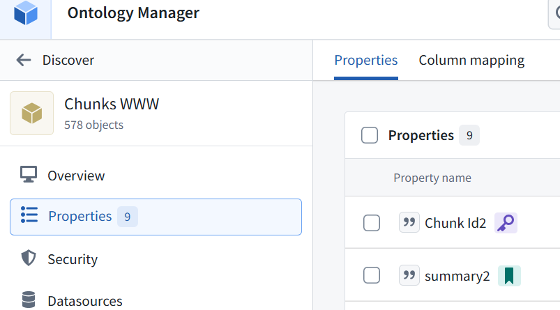
- The actual text shown is the ontology object def’s property that is marked in ontology as the “Title”
- That is summary2 (see pic2), the ai-generated text version of original chunk text
Diagram 9: P2: The related chunks shown in the left widget
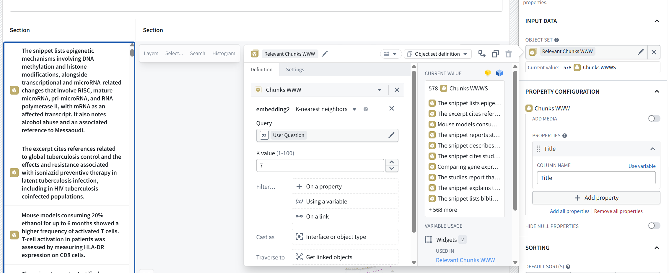
Diagram 10: P2: The ontology for the left widget
FDE: Yes. Your explanation is correct, with one wording adjustment:
- The search does not return seven embeddings; it returns the seven Chunk objects whose embeddings are nearest to the question.
A precise description is:
- The left widget uses the Relevant Chunks WWW object-set variable.
- Its base object type is Chunks WWW.
- It performs a K-nearest-neighbors search against embedding2.
- embedding2 was generated from the AI-created summary2.
- User Question supplies the semantic-search query.
- K = 7 returns the seven most relevant Chunk objects.
- The widget displays each object’s Ontology Title property.
- The Title property is summary2, so users see an AI-generated summary rather than the original content2.
User question → search summary embeddings → return 7 Chunk objects → display each Chunk’s summary2
ME: quite compllicated…
FDE: Yes—mostly because Foundry exposes every implementation layer separately. The left widget’s business meaning is simply: Show the seven document passages most relevant to the user’s question. The implementation underneath is: Question → compare with summary embeddings → select 7 chunks → display summaries Everything else—object types, variables, title-property mappings, and widget configuration—is platform wiring.
ME: no explanation in demo doc… we are supposed to all figure this out for selves,,,,
is the problem the doc or the fact that i am not the typical customer who can figure this out quickly?
FDE: The primary problem is the documentation—not you.
The Speedrun appears written as a procedural recipe for users who already understand:
- Embeddings and nearest-neighbor retrieval
- RAG architecture
- Ontology object sets and title properties
- Workshop variables
- Vertex templates and links
An experienced Foundry implementer might infer the wiring faster, but even that person should not have to reverse-engineer the demo’s purpose from UI configuration.
The documentation should have started with:
Question → find 7 chunks using summary embeddings → display their summaries → send 10 chunks’ original text to GPT‑4o → generate an answer → optionally visualize extracted entities
Then each UI instruction would have had clear meaning. Instead, it explains which controls to click without explaining the architecture, and even blurs the functional RAG path with the optional Vertex path. That is a documentation-design problem.
C1.5 P3 RIGHT (create diagram with linked keywords-chunks / NO AI)
(this is a very rough draft)
This right widget does not use AI
FDE: the answer workflow does not traverse Entity objects or Chunk–Entity links. It searches Chunk embeddings directly. The Entity graph is displayed alongside the answer, but it is not used to generate it.
More importantly, the introduction is misleading when it says: “Leverage this graph and respond to your questions…” Based on the AIP Logic you showed, the answer workflow does not traverse Entity objects or Chunk–Entity links. It searches Chunk embeddings directly. The Entity graph is displayed alongside the answer, but it is not used to generate it. Likewise: “See the segment of your knowledge graph used to formulate the answers” is only partially true. The relevant Chunk objects supplied the reference text, but their graph relationships and linked Entity objects did not formulate the answer.
TOC:
- C1.5.1 Pipeline for P3
- C1.5.2 Entities / links » ontology (EXPLAIN)
- C1.5.3 Vertex graph (EXPLAIN)
- C1.5.4 Vertex template (EXPLAIN)
- C1.5.5 Template usage in the UI
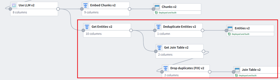
C1.5.1 Pipeline for P3
Diagram 11: P3: The ontology for the right widget
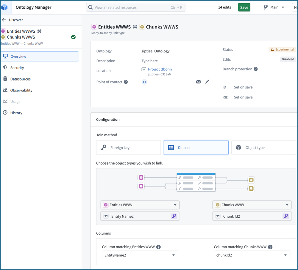
C1.5.2 Entities / links » ontology (EXPLAIN)
Diagram 11b: P3: The ontology for the right widget
C1.5.3 Vertex graph (EXPLAIN)
C1.5.4 Vertex template (EXPLAIN)
Diagram 12: P2: The ontology for the left widget
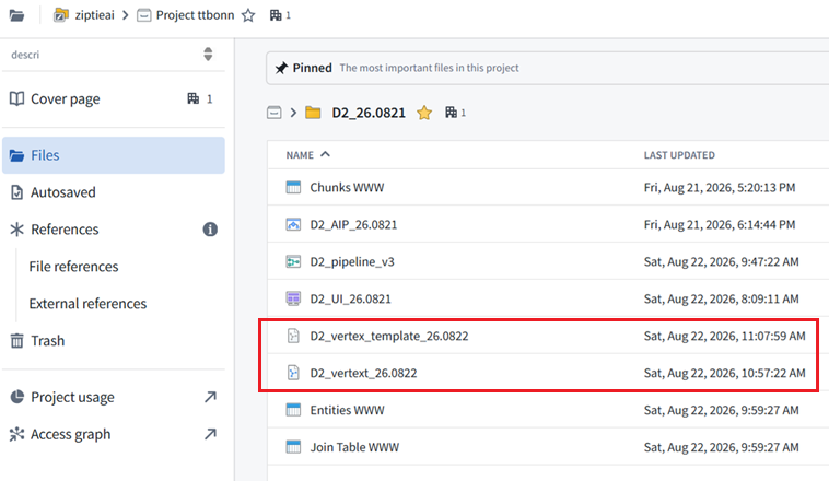
C1.5.5 Template usage in the UI
Diagram 13: P2: Using the vertex template in the UI
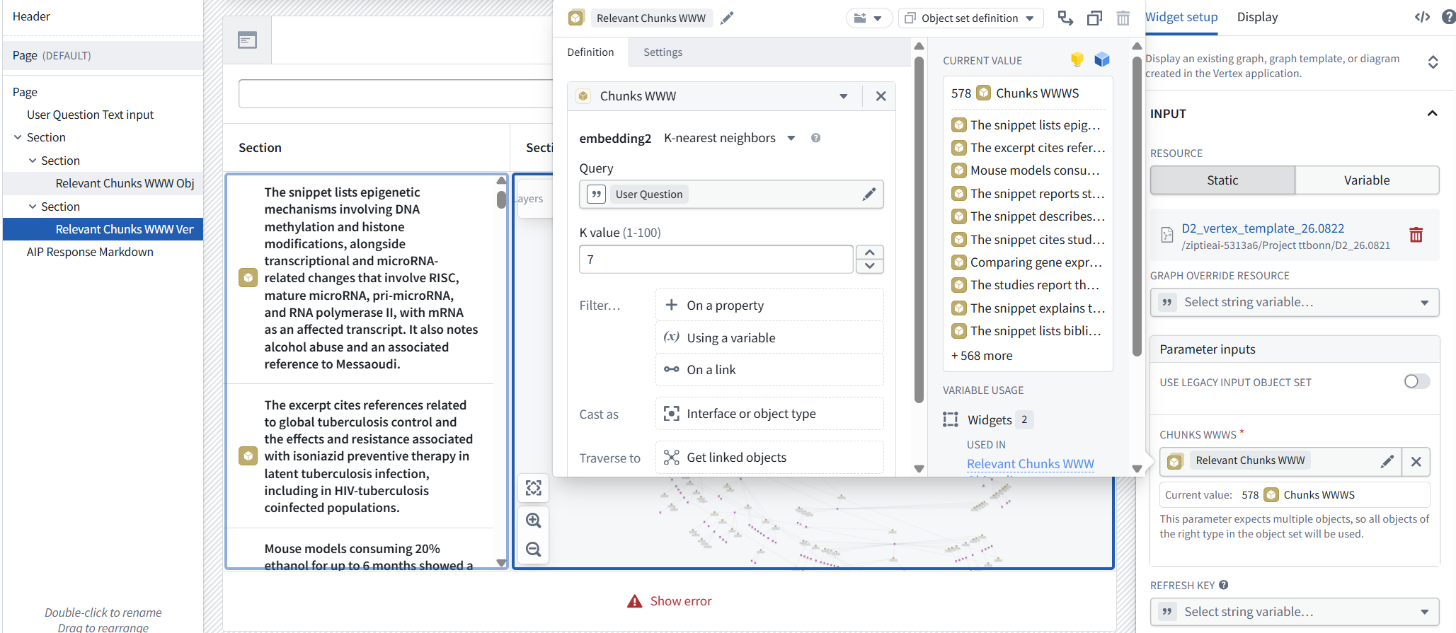
ME: in the vertex graph i never defined what should be displayed for hte “Chunks WWW” and “Entities WWW” object types… is this automaticaly whatever property is the title?
FDE: By default, Vertex uses each object type’s Title property as the node’s main label.
In your demo:
- Chunks WWW: summary2 is the Title, so gold nodes display the chunk summary.
- Entities WWW: EntityName2 is the Title, so purple nodes display the entity/keyword.
You can override or augment this in the Vertex template using layer styling, subtitles, and extended labels.
Object and edge display options / Extended labels https://www.palantir.com/docs/foundry/vertex/graphs-display-options#extended-labels
ME: and for the right widget (vertex): “Parameter inputs” = (see pic). this is an embedding???
or is the selecttion based on the embedding (this is the object type “Chunks WWW” filter.. the input to the vertex is still the property that is the title?
The Vertex parameter receives the selected Chunk objects, not the embeddings and not only the Title property.
Flow:
User Question → search embedding2 → select 7 Chunk objects → pass those complete objects into Vertex
Each Chunk object includes all its properties:
- summary2
- content2
- embedding2
- chunkId2
- Page/document metadata
Vertex then uses the object type’s Title property (summary2) only to label the gold nodes.
So:
- Embedding: determines which chunks are selected.
- Parameter input: passes those selected Chunk objects.
- Title property: determines the text displayed on each Chunk node.
- Vertex template: follows their links to the Entity nodes.
26.0826 (v1 26.0713)